Understanding IO Links and Data Connectivity
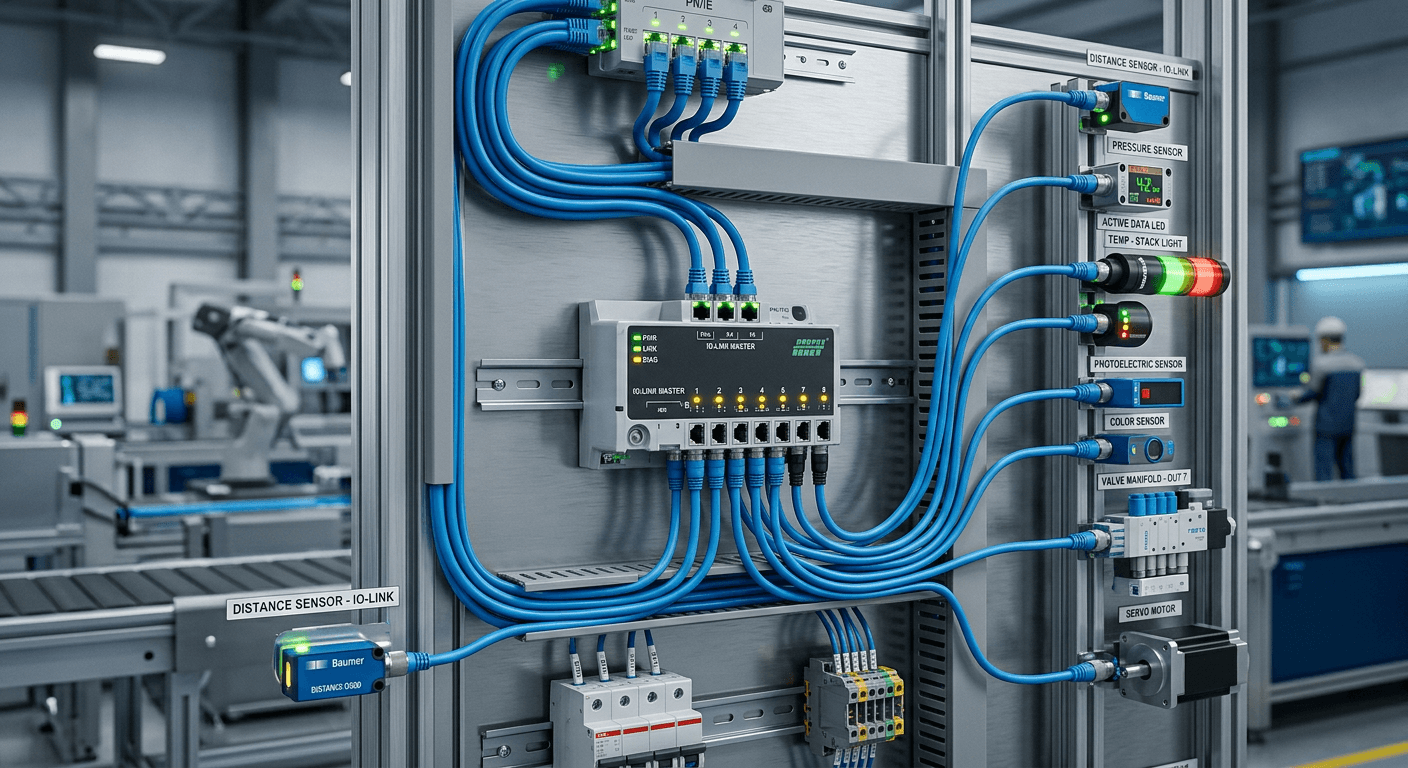
Modern industrial automation relies on the seamless exchange of information between field-level devices and control systems. The io link protocol has emerged as the definitive standard for point-to-point communication, providing a robust, vendor-neutral framework for intelligent sensors and actuators. By moving beyond traditional binary signaling, this technology enables enhanced diagnostics, remote configuration, and detailed parameterization of field devices.
Quick Summary {#quick-summary}
IO-Link is an open-standard, point-to-point serial communication protocol used to connect sensors and actuators to an automation system. It enables bidirectional data exchange, allowing controllers to receive diagnostic information and push configuration parameters to devices while maintaining compatibility with standard binary digital I/O architectures for flexible factory deployment.
- Bi-directional data transfer between devices and controllers.
- Advanced diagnostic capabilities for predictive maintenance.
- Automated device replacement through parameter storage.
- Full backward compatibility with standard digital inputs and outputs.
Table of Contents {#table-of-contents}
- Foundations of IO-Link Technology
- Data Transmission and Communication Modes
- Comparison of Link Architectures
- Advantages of Digital Field Connectivity
- Implementation and Integration Strategy
- Real-World Industrial Insights
- FAQ
- Recommended Reads

Foundations of IO-Link Technology {#foundations-of-io-link-technology}
At its core, the io link protocol acts as a digital bridge between traditional sensor technologies and high-level control networks. Unlike analog signals, which are susceptible to electromagnetic interference and signal degradation over distance, IO-Link transmits data digitally. This ensures that the integrity of the process value remains constant from the sensor face to the PLC, regardless of the cable length or environment.
The system utilizes a standard three-wire unshielded cable, which keeps installation costs low and simplifies the engineering process. By leveraging existing cable infrastructure common in many automation setups, organizations can upgrade their field-level communication without extensive rewiring. This simplicity is vital for modernizing older production lines into smart, data-driven manufacturing environments. You can explore how these industrial connectivity solutions facilitate more reliable data transfer in complex manufacturing cells.
Data Transmission and Communication Modes {#data-transmission-and-communication-modes}
Communication in an IO-Link environment is categorized into two primary types: process data and service data. Process data is the cyclic information exchanged between the device and the master in real-time, such as pressure readings, distance measurements, or temperature values. This data is essential for the immediate control loops of the machinery.
Conversely, service data involves a-cyclic exchanges, such as device parameters, calibration settings, and error logs. These are requested only when needed, reducing network traffic. Furthermore, the protocol handles event data, which provides status updates like "sensor dirty" or "device overheating." This granular level of insight is crucial for implementing predictive maintenance strategies, allowing teams to resolve issues before they result in unplanned downtime.
Comparison of Link Architectures {#comparison-of-link-architectures}
In the diverse landscape of industrial connectivity, various terminology surfaces. While specific labels such as v link or v-link are often used in niche proprietary contexts, they generally refer to specialized vertical integration paths or dedicated bus segments. Similarly, terms like c-link and s-link frequently denote specific clocking or synchronization configurations within hardware-level communication modules.
| Feature | IO-Link | Analog Signaling | Traditional Digital I/O |
|---|---|---|---|
| Signal Type | Digital (Bi-directional) | Continuous (4-20mA) | Binary (On/Off) |
| Diagnostic Data | High (Detailed) | Low/None | None |
| Configuration | Remote / Software | Manual (Potentiometer) | None |
| Wiring Complexity | Low (Standard 3-wire) | Moderate (Shielded) | Moderate (Multi-wire) |
Pro Tip: Always utilize the integrated parameter server features in modern masters. This allows for seamless hot-swapping of sensors, as the master automatically pushes the saved configuration to a replacement device without manual intervention.
Advantages of Digital Field Connectivity {#advantages-of-digital-field-connectivity}
One of the most significant benefits of digital connectivity is the drastic reduction in commissioning time. With remote parameterization, engineers can configure thousands of sensors from the central controller or an engineering workstation. This eliminates the need for manual testing of each device on the factory floor, significantly speeding up the startup phase of new projects.
Additionally, the ability to store device configurations centrally provides a safety net during hardware failures. If a sensor fails, a technician can simply plug in a generic replacement unit, and the master will restore the correct settings instantly. Integrating these advanced sensor frameworks into your workflow ensures that downtime is minimized to the time taken for a simple physical swap rather than manual re-calibration.
Implementation and Integration Strategy {#implementation-and-integration-strategy}
Implementing IO-Link requires a clear understanding of the network topology. A typical setup includes an IO-Link master, which acts as the gateway between the field devices and the fieldbus (e.g., PROFINET, EtherNet/IP, or EtherCAT). Proper planning involves ensuring that the power budget for the ports is sufficient for the connected actuators.
When scaling, consider the physical placement of the master modules. Using decentralized I/O blocks allows for shorter cable runs to sensors, which reduces the potential for localized interference. By keeping the connection logic centralized within the PLC code and distributing the hardware appropriately, you maintain a clean, maintainable architecture that is easy to troubleshoot when service is required.
Real-World Industrial Insights {#real-world-industrial-insights}
In high-volume manufacturing, the primary advantage observed is the reduction in mean time to repair (MTTR). Technicians often report that being able to view the health status of a sensor through the HMI screen—rather than climbing onto machinery—improves safety and efficiency significantly. Furthermore, using IO-Link to detect when a machine element is wearing out—such as a pneumatic cylinder showing signs of slowed cycle times—allows for maintenance to be performed during scheduled breaks.
However, it is vital to acknowledge the limitation of cable lengths. While the standard allows up to 20 meters, exceeding this can lead to issues with signal timing. Experienced engineers plan their cabinet locations to ensure that no device exceeds the 20-meter threshold, guaranteeing that the signal remains within the operational tolerances required for high-speed synchronization.
FAQ {#faq}
Is IO-Link compatible with non-IO-Link sensors? Yes. Most IO-Link masters support "Standard I/O" (SIO) mode, allowing you to plug in standard digital sensors into the same port without any loss of function.
What is the maximum speed of IO-Link communication? There are three communication modes (COM1, COM2, COM3), with COM3 being the fastest at 230.4 kbit/s. This is sufficient for the vast majority of industrial sensor applications.
Does IO-Link require specialized cables? No. It uses standard unshielded M12 or M8 cables. This is a key advantage as it reduces costs and simplifies inventory management for spare parts.
Can I power actuators through an IO-Link port? Yes, but you must monitor the current consumption. Port classes (Class A vs. Class B) determine how much power is available for the connected device.